
High Speed Rotary Union Guide: 20,000 RPM Explained
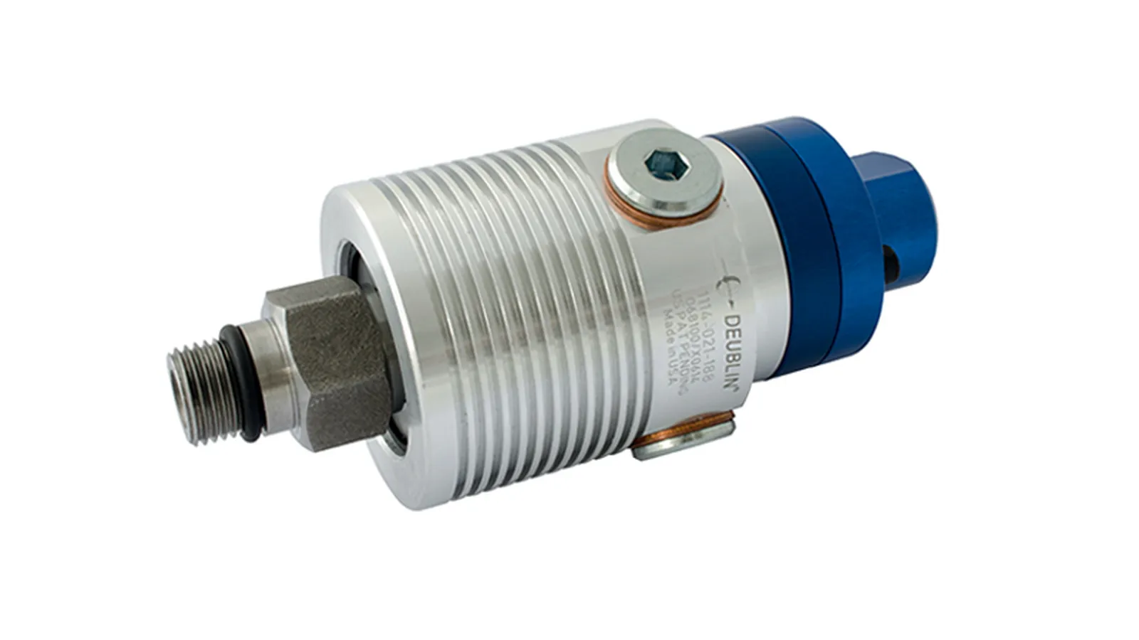
Table of Contents
At 20,000 RPM, a 10 mm rotary union seal face travels at roughly 10.5 m/s — and that velocity, multiplied by the pressure behind it, decides whether the union lasts five years or five weeks. Every gram of imbalance and every micron of misalignment is amplified into friction heat and seal wear. High-speed rotary unions are a different breed from standard unions: precision bearings, minimal rotating mass, low-friction seal faces, and installation rules that punish shortcuts. This guide covers how they work, how to calculate their real limits, and how to get service life out of spindle-duty unions.
You will learn what counts as high speed, how to convert RPM into seal face velocity, how pressure and temperature derate the speed rating, which seal materials and lubrication strategies survive continuous high-speed duty, and the installation and maintenance practices that separate long service life from premature failure. Figures are given as typical ranges for standard spindle-duty designs unless a formula or published standard is cited.
The Snapshot
- High speed for rotary unions starts around 6,000 RPM; spindle-duty unions run 10,000–20,000+ RPM.
- Seal face velocity is the real limit — v = π × d × n / 60,000. At 20,000 RPM a 10 mm face runs at 10.5 m/s.
- Design differences: precision angular-contact hybrid bearings, minimal rotating mass, lapped low-friction faces, G2.5 or better balancing.
- Through-spindle coolant unions carry cutting fluid at up to 70 bar while the spindle spins at full speed — the highest pressure × velocity combination in rotary unions.
- Ratings derate: the headline RPM is only valid at low pressure and low temperature; at 70 bar coolant the usable speed can drop to roughly half.
- Installation: align to 0.01–0.05 mm TIR and balance the rotating assembly — runout at 20,000 RPM destroys seals in hours.
- Life: with correct installation and clean media, 8,000–15,000 hours before seal service is typical.
What Counts as High Speed?
Standard rotary unions are typically rated to 3,000–6,000 RPM. Above that, the physics change: seal face velocity rises, friction heat generation grows, and rotating mass creates imbalance forces that scale with the square of speed. The industry treats roughly 6,000 RPM as the line where you move to a purpose-built high-speed design.
CNC spindles are the biggest high-speed application. A machining-center spindle runs 10,000–30,000 RPM, and the rotary union on the back of the spindle feeds coolant, air, or oil through the rotating tool. The same class of union appears on:
- High-speed machining centers — through-spindle coolant (TSC) at 20–70 bar, continuous duty at 10,000–20,000 RPM.
- Grinding machines — coolant and sometimes air through the wheel spindle; small seal faces, very high RPM, and fine filtration because grinding swarf is aggressively abrasive.
- Balancing machines — air or oil at moderate pressure but 12,000–30,000 RPM on small spindles.
- Test and turbine rigs — oil feed to high-speed rotors, often with strict cleanliness requirements and long continuous runs.
- Packaging and printing rolls — lower speeds, but the same precision-bearing family where runout at the seal matters for leak-free service.
The practical operating limit is not RPM alone; it is the combination of pressure, speed, and temperature at the seal face. A union rated 20,000 RPM at 10 bar air can drop to roughly 8,000 RPM at 70 bar coolant. Always check the rating at your combination, not just the headline RPM — the wider selection process is covered in our rotary union guide.
Speed Math: RPM vs Seal Face Velocity
Rotary union ratings are quoted in RPM, but the seal does not know RPM — it knows the linear speed at which the two faces slide over each other. That velocity is:
v = π × d × n / 60,000
where v is the seal face velocity in m/s, d is the mean seal face diameter in mm (the average of the face outer and inner diameters), and n is the rotational speed in RPM.
Worked example: a union with a 10 mm mean seal face diameter at 20,000 RPM runs at π × 10 × 20,000 / 60,000 = 10.5 m/s. Doubling the face diameter doubles the velocity at the same RPM — which is why a compact seal face is a design goal, not a cost saving.
| Face Ø (mm) | 6,000 RPM | 10,000 RPM | 15,000 RPM | 20,000 RPM |
|---|---|---|---|---|
| 8 | 2.5 m/s | 4.2 m/s | 6.3 m/s | 8.4 m/s |
| 10 | 3.1 m/s | 5.2 m/s | 7.9 m/s | 10.5 m/s |
| 15 | 4.7 m/s | 7.9 m/s | 11.8 m/s | 15.7 m/s |
| 20 | 6.3 m/s | 10.5 m/s | 15.7 m/s | 20.9 m/s |
Where does d come from? On a face-type seal, the mean diameter sits between the inner and outer edge of the lapped sealing land — for example, a seal land with an 8 mm inner and 12 mm outer diameter has a mean diameter of 10 mm. Ask the supplier for the face mean diameter of the units you are comparing; it is the number that makes RPM ratings comparable.
Two practical conclusions. First, two unions with the same RPM rating can have very different face speeds if their seal diameters differ — compare velocity, not RPM, when you evaluate designs. Second, friction heat at the face is roughly proportional to face velocity times contact pressure, so every m/s you shave off the design reduces the heat input to the seal and the bearing pack. This is also why larger-bore unions carry lower speed ratings: a 20 mm face at 20,000 RPM runs at 20.9 m/s, roughly double a 10 mm face at the same speed. If your application needs the higher flow of a larger bore, expect either a lower maximum speed or a more sophisticated seal design.
The PV Limit: Pressure × Velocity
Rotary union performance is bounded by the PV value — the product of working pressure and seal face velocity. The seal must hold pressure against a face sliding at speed; both raise the heat and wear load on the faces. Manufacturers publish a speed envelope, not a single RPM figure, and the usable speed falls as pressure and temperature rise.
Physically, the PV limit is a heat limit. Friction power at the face scales with contact pressure times sliding velocity — the same product the PV number captures. Beyond the material's PV envelope, the face cannot shed the heat it generates, the fluid film breaks down, and wear accelerates non-linearly. This is why the same union can be perfectly happy at 20,000 RPM with air and marginal at 8,000 RPM with 70 bar coolant.
The derating pattern below is typical for standard spindle-duty designs (pressure-balanced TSC unions behave differently — see the coolant section). Model data sheets govern.
| Working pressure | Usable speed (% of rated max) |
|---|---|
| 0–10 bar | 100% |
| 10–30 bar | ~85% |
| 30–50 bar | ~65% |
| 50–70 bar | ~40–50% |
| Media temperature | Usable speed (% of rated max) |
|---|---|
| Below 60 °C | 100% |
| 60–100 °C | ~80% |
| 100–150 °C | ~60% — special seals and grease required |
| Above 150 °C | High-temperature design required |
Where both factors apply, the two deratings combine multiplicatively as a first estimate: a union run at 40 bar (~65%) and 80 °C media (~80%) is good for roughly 52% of its headline speed. If your duty sits in the high corner of both tables, expect the supplier to quote a pressure-balanced or reduced-diameter seal design rather than a standard unit.
Design Differences
What makes a high-speed union different from a standard one:
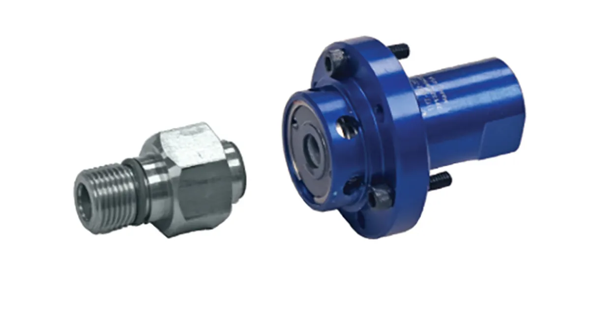
- Bearings: precision angular-contact ball bearings, typically with a 15–25° contact angle, selected and preloaded for high-speed spindle duty. Angular-contact bearings carry combined radial and axial loads and keep the seal faces square under load; deep groove ball bearings appear in lighter-duty high-speed unions where axial load is minimal. Hybrid ceramic bearings (silicon nitride balls on steel races) are standard above roughly 10,000 RPM: the lower-density ceramic balls exert less centrifugal force at speed, run cooler, and last longer.
- Rotating mass: the rotating components are minimized and lightened. Lower inertia means less energy to spin up, less heat, and lower gyroscopic loads on the bearings during spindle acceleration and deceleration.
- Seal faces: low-friction face materials (carbon graphite against silicon carbide or ceramic) that run with minimal drag and heat, lapped flat to a fraction of a micron.
- Balancing: the rotating assembly is dynamically balanced to G2.5 or better per ISO 1940-1. At 20,000 RPM, G2.5 permits a residual unbalance eccentricity of about 1.2 µm (e = 9549 × G / n, with e in µm) — a tight, measurable standard that standard unions do not meet.
- Cooling: some designs carry air or oil cooling channels through the housing around the bearing area, or rely on the coolant flow itself to remove bearing heat.
These are not optional upgrades. They are what let the union survive continuous high-speed rotation without burning up. A standard union pressed into 15,000 RPM duty fails from bearing heat and seal wear within days.
Seal Design and Face Materials
The seal face pair is the heart of a high-speed union. Two flat rings — one rotating with the rotor, one stationary in the housing — are held in light contact by springs and fluid pressure while a thin film of the media separates them.
- Carbon graphite vs silicon carbide — the workhorse combination. The carbon face is self-lubricating, tolerates brief dry running, and wears preferentially, protecting the harder SiC face. It handles moderate PV and is the default for air and light coolant duty.
- Silicon carbide vs silicon carbide — hard-on-hard, for high-pressure coolant where the fluid film reliably separates the faces. Wear life is long, but friction is higher and dry running damages the faces quickly, so this pair is only specified where lubrication is guaranteed.
- Carbon vs alumina ceramic — an older, economical pair still found in air and vacuum service.
- Tungsten carbide faces — for abrasive media or where the faces see erosive particles; higher cost and weight.
Two geometric details matter as much as the material. First, face flatness: high-speed faces are lapped to roughly one to two light bands (about 0.3–0.6 µm), because a face that is not flat cannot maintain a stable film. Second, face width: the seal land is kept narrow — typically a millimetre or two — to minimize the sliding area and therefore friction torque and heat.
In pressure-balanced designs, the geometry is arranged so that the hydrostatic opening force from the media grows with pressure, holding the closing force nearly constant. This is what allows a 70 bar coolant union to run at speed without the faces being forced together harder as pressure rises.
Wear mechanism: in normal operation the faces do not touch — they ride on a fluid film a fraction of a micron thick. Wear happens when the film breaks down: at startup and shutdown (boundary lubrication), during pressure spikes, or when debris bridges the film. That is why controlled ramp-up and clean media extend face life more than any material upgrade.
Through-Spindle Coolant
Through-spindle coolant (TSC) is the most demanding high-speed union application. Cutting fluid at 20–70 bar passes through the rotating spindle to the tool tip, cooling the cut and flushing chips while the spindle runs at full speed.
The union must seal high pressure against a face spinning at 15,000+ RPM — the highest pressure × velocity combination in rotary unions. Dedicated TSC unions use hard faces, precision bearings, and pressure-balanced seal designs to keep face contact stable under pressure.
Two configurations exist: single-channel TSC (coolant only) and combined air/coolant, where a second channel supplies pilot air for tool blow-off or spindle purge. Media quality decides seal life: water-miscible emulsions at 5–10% concentration are standard, and filtration to 25–50 µm is typical — abrasive fines from the machining process are the main reason TSC seal faces wear out early.
Pressure spikes matter as much as steady pressure. Pump start, tool change, and valve switching can double the line pressure for a few milliseconds; a union selected on steady-state pressure alone may face-float or leak under spikes. State both steady pressure and expected spikes when you spec the unit.
Cooling and Lubrication Strategies
Heat is the enemy at 10,000+ RPM. Friction at the seal face generates tens of watts for a typical lubricated face at 10 m/s (a friction force of a few newtons times face velocity), and the bearing pack adds more. That heat has to leave the union — the strategy depends on the duty:
- Water-based coolant flush — in TSC and coolant-flooded applications the media itself carries heat away from the seal cavity. This is the most effective cooling path and one reason coolant unions survive speeds that air unions cannot.
- Oil mist (oil-air) lubrication — bearings are fed a fine, metered mist of oil, typical for the highest DN values (bearing bore in mm × RPM above roughly 400,000–500,000). The air stream carries the oil and the heat, and the small oil volume avoids the churning losses of flooded lubrication.
- Low-fill grease — for moderate high-speed duty, bearings are packed with 25–35% fill of a high-speed lithium-complex or synthetic grease and re-lubricated on schedule. Over-packing traps heat — more grease is not better.
- Air purge — a small continuous air flow through the housing prevents coolant mist or swarf from entering the bearing cavity and keeps the seal environment dry in air-only service.
Bearing housing temperature is the best field indicator of lubrication health. A typical spindle-duty union runs with the housing warm but touchable — roughly 40–60 °C; sustained operation above 70 °C points to seal drag, grease starvation, or a blocked cooling path and should be investigated rather than accepted.
Selection Parameters
For a high-speed union, provide these parameters:
- Speed: maximum spindle RPM, continuous or intermittent — plus how long the spindle spends at maximum.
- Media: coolant (and its concentration), air, oil, or combination. Seal materials and face pairs are chosen from this.
- Pressure: maximum coolant or air pressure at the union, including expected spikes.
- Temperature: media and ambient — coolant can arrive hot from the chiller loop, and hot media derates the speed rating.
- Port size: matching the spindle's coolant inlet (commonly G1/8 to G3/8).
- Mounting: how the union attaches to the spindle back — thread, flange, or drawbar-integrated.
- Duty cycle: continuous running, frequent start/stop cycling, or long periods at standstill with coolant pressure on. Cycling duty stresses faces and bearings differently from steady running.
- Cleanliness: filtration level of the media — below 50 µm is typical; finer is better for seal life.
The supplier should confirm the rating at your speed × pressure × temperature combination, not just quote a model number. If the vendor only gives you a headline RPM, ask for the derating curve at your operating pressure.
Installation & Balancing
High-speed unions tolerate almost no misalignment. The rotating faces are designed to run parallel to within a fraction of a micron; if the union bore and the spindle axis are not concentric, the faces separate and re-contact on every revolution — that is a wear and vibration generator, not a seal.
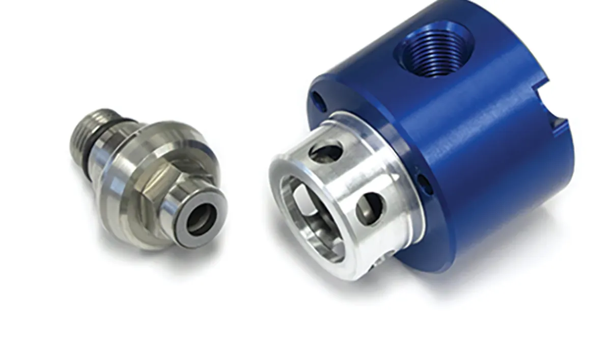
- Concentricity: target 0.01 mm TIR (total indicator reading) between the union bore and the spindle axis, and no more than 0.05 mm in the field. Check with a dial indicator on the mounted union while rotating the spindle by hand; shim the mounting flange to correct.
- Squareness / end runout: keep the mounting face square to the axis to the same order — a tilted face forces the seal to track a wobble on every revolution.
- Balance the assembly: the rotating combination of union, adapter, and tool holder should be dynamically balanced together to G2.5 or better. Unbalance force grows with the square of speed: a 0.5 kg assembly with 1.2 µm residual eccentricity at 20,000 RPM generates roughly 2.6 N of centrifugal force (F = m × e × ω²) — enough to shake a light spindle and hammer the bearings.
- Support the supply line: use flexible hose, never rigid pipe, so the union body does not carry line load or transmit machine vibration. Leave a service loop for thermal growth of the spindle.
- Counter-hold when tightening: torque the fluid connections against the union body, not through the bearings.
- Verify rotation direction and lubrication before full-speed operation.
- Ramp up: run at low speed first to check for vibration, then bring up to full speed in steps, watching housing temperature.
Failure Modes and Countermeasures
Most high-speed union failures fall into three families: overheating, vibration, and premature seal wear. They are related — vibration accelerates seal wear, and seal drag produces heat — so treat them as a system.
Overheating. Sustained housing temperature above roughly 70 °C means the seal or bearings are generating more heat than the design removes. Common roots: over-packed grease (which insulates), coolant flow below the minimum, or running above the derated envelope. Measure temperature at the same point every time — trends matter more than absolute values.
Vibration. High-speed vibration is almost always unbalance or bearing damage. Because unbalance force scales with the square of speed, a small imbalance invisible at 3,000 RPM becomes destructive at 20,000 RPM. Log vibration at a fixed speed and investigate any upward trend before it becomes a spindle teardown.
Premature seal wear. If faces wear out in weeks instead of years, look first at media cleanliness and alignment — the two parameters that dominate face life — then at dry-running events and pressure spikes.
| Symptom | Likely cause | Countermeasure |
|---|---|---|
| Housing runs hot (>70 °C) | Seal drag, over-packed grease, blocked coolant path, wrong lubricant | Check media flow and filtration, re-lubricate to spec, verify speed within derated envelope |
| Vibration at speed | Unbalanced assembly, bearing wear, resonance, loose mount | Re-balance to G2.5, inspect bearings, check mounting torque and hose strain |
| Coolant leak at standstill | Worn faces, debris trapped between faces, spring fatigue | Flush, inspect, replace seal kit |
| Leak only under pressure | Pressure spikes, thermal shock, face lift-off | Add accumulator or relief, warm up gradually, confirm pressure-balanced design |
| Short seal life (repeated) | Dirty media, misalignment, dry running, over-speed | Improve filtration to 25–50 µm, re-check concentricity, confirm lubrication is always on |
| Bearing noise or rumble | Grease starvation, preload loss, contamination ingress | Re-lubricate on schedule, check air purge, replace bearing pack |
Dry running is the fastest way to destroy a high-speed union. Hard-on-hard faces (SiC/SiC) can be damaged within seconds without lubrication; even carbon faces survive only briefly. If your process can lose coolant flow while the spindle spins, add a flow switch interlock rather than relying on operator attention.
Service Life & Seals
High-speed unions wear their seal faces faster than standard unions because face velocity is higher. Typical service life is 8,000–15,000 hours with correct installation — less if coolant is dirty, pressure spikes are common, or the unit runs beyond its derated envelope.
Extend life with clean, filtered media, correct alignment, scheduled lubrication, and monitoring the three failure signs — coolant leak, overheating housing, or vibration. Replace the seal kit on schedule rather than on failure; on a machining center, an unplanned seal failure means a spindle teardown.
Data to log: hours run, housing temperature, supply pressure, filter ΔP, and vibration. With those five numbers recorded weekly, a maintenance team can replace the seal kit during a scheduled window instead of during a breakdown. The union itself is cheap; the unplanned spindle teardown is not.
A maintenance schedule that matches the duty:
| Interval | Task |
|---|---|
| Daily | Visual leak check; housing temperature by hand; listen for bearing noise |
| Weekly | Check supply pressure and filter differential pressure (ΔP) |
| Monthly | Re-lubricate per schedule; verify mounting torque; log vibration trend |
| Quarterly | Replace or clean filter elements; inspect hoses and service loop |
| Annually / ~8,000 h | Seal kit replacement; bearing inspection; balance verification |
Keep a seal kit on the shelf for each union. The rebuild itself is quick; the disassembly of the spindle to reach the union is the expensive part.
Quick Answers
At what speed do I need a high-speed rotary union?
Above roughly 6,000 RPM continuous, or any time the union is on a CNC spindle, use a purpose-built high-speed design.
What is through-spindle coolant?
Cutting fluid delivered through the rotating spindle to the tool tip via a rotary union, typically at 20–70 bar, for cooling and chip flushing.
Why do my high-speed unions fail early?
Most common causes: misalignment, unbalanced assembly, dirty coolant, dry running, or running beyond the PV rating (pressure × speed).
Can I use a standard rotary union on a spindle?
Not for continuous duty — standard seals and bearings overheat at high RPM. Use a high-speed-rated union.
How do I calculate seal face velocity?
Use v = π × d × n / 60,000, where d is the mean seal face diameter in mm and n is speed in RPM. A 10 mm face at 20,000 RPM gives 10.5 m/s.
What does a G2.5 balance grade mean?
It is the balance quality grade per ISO 1940-1. At 20,000 RPM, G2.5 allows a residual unbalance eccentricity of roughly 1.2 µm — the rotating assembly must be dynamically balanced to that standard, not just statically.
Spec the Union, Not the Downtime
You now have the numbers: the velocity formula, the derating pattern, the materials, and the maintenance schedule. The next step is matching those numbers to a unit — and that is where the details (port size, mounting, pressure spikes, coolant concentration) decide whether you get 10,000 hours or 10 days.
Browse the high-speed rotary union range for spindle-duty units rated to 20,000 RPM, or send your speed, pressure, and port details and get a model recommendation with the derating curve for your combination — not just a headline RPM.
NEXT STEP
Ready to Spec the Right Rotary Union?
Send us your requirements — our team responds within 24 hours with pricing and lead time.
Written by
LOOP ENGINEERING TeamRotary union engineering specialist. LOOP ENGINEERING helps machine builders and maintenance teams source factory-direct rotary unions.